
410.310M
HSK Dial Indicator Spindle Taper Gauge Manual
")
Instruction manual for the dial indicator spindle taper gauge (410.310)
![]() PDF Data Sheet: HSK Dial Indicator Spindle Taper Gauge Manual (410.310M)
PDF Data Sheet: HSK Dial Indicator Spindle Taper Gauge Manual (410.310M)
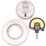
Instructions1. Thoroughly clean the Master Taper and Setting Ring (we recommend using lint-free wipes).
2. Insert the Master Taper into the Setting Ring so that the dial indicator mounting hole is aligned with the 0.10 groove.
3. Using a hex wrench, install the Dial Indicator such that the indicator reads zero when positioned in the 0.10 groove. The fine adjustment on the Dial Indicator can be used if needed.
With the Dial Indicator reading zero, the measurement distance l2 in relation to the taper diameter d2 is set to zero (per ISO 12164-2).
When finished, lightly oil measuring surfaces to protect in storage.
Measuring ExampleBecause of the 1:10 taper of the HSK, the dial gauge shows the d2 deviation multipled by a factor of 10. For example, for HSK-A 63, the nominal dimension d2 is 47.998 mm. If the spindle being checked has an actual diameter d2 of 47.997 mm, the Dial Indicator displays -0.01.
(See PDF data sheet for more examples)
For more information regarding this item (HSK Dial Indicator Spindle Taper Gauge Manual) or other items, fill out the form below
or contact our office directly:
Telephone: 815-962-5600
Fax: 815-962-4600
Location: 304 North Main St, Suite 104, Rockford, IL 61101-1101 USA
Email: infο@ΤΑCRοckfοrd.cοm
Related
Dial Indicator Spindle Taper Gauges
To ensure sustained accuracy at HSK interfaces, we recommend comparison measuring of the geometry of HSK tool shanks and spindles at regular intervals. These checks should become more frequent with an increased change rate at the interface. Calibration on request.