
100.311
Drawbar Clamping Forces
")
Drawbar forces in this document are sourced from international standards and gripper manufacturers. This information is for reference only: For specifications applicable to a specific machine, the machine builder should be contacted. Depending on the application, it is typical for a machine builder to design a machine for higher or lower forces.
Drawbar forces in this document are sourced from international standards and gripper manufacturers. This information is for reference only: For specifications applicable to a specific machine, the machine builder should be contacted. Depending on the application, it is typical for a machine builder to design a machine for higher or lower forces.
Steep Taper – ASME B5.50 (CAT/ANSI)Note: ASME B5.50 is commonly referred to as CAT/ANSI. Forces shown are "Suggested Drawbar Pull Force".
• Steep Taper CAT30: 5340 N / 1200 lb-f
• Steep Taper CAT40: 10230 N / 2300 lb-f
• Steep Taper CAT45: 17790 N / 4000 lb-f
• Steep Taper CAT50: 22240 N / 5000 lb-f
• Steep Taper CAT60: 57830 N / 13000 lb-f
Steep Taper – BERG SSK GripperNote: Forces are maximum allowable for the gripper. These forces should be considered high for the machine taper.
• Steep Taper SK30: 10000 N / 2250 lb-f
• Steep Taper SK40: 18000 N / 4050 lb-f
• Steep Taper SK45: 25000 N / 5600 lb-f
• Steep Taper SK50: 35000 N / 7870 lb-f
• Steep Taper SK60: 70000 N / 15740 lb-f
HSK – ISO 12164-1Note: Forces shown are "Recommendations for use and application. Forces will ensure that the portion acting on the flange surface is never less than 75% of the total. Lower clamping forces can be sufficient when operational loads are low (e.g. cutting forces in finish machining.) Conversely, higher clamping forces can be required when high operational loads are encountered (e.g. cutting and feed forces in heavy machining)."
• HSK-A/C/E 25: N/A
• HSK-A/C 32: 5000 N / 1120 lb-f
• HSK-A/C 40: 6800 N / 1530 lb-f
• HSK-A/C 50: 11000 N / 2470 lb-f
• HSK-A/C 63: 18000 N / 4050 lb-f
• HSK-A/C 80: 28000 N / 6290 lb-f
• HSK-A/C 100: 45000 N / 10120 lb-f
• HSK-A/C 125: 70000 N / 15740 lb-f
• HSK-A/C 160: 115000 N / 25850 lb-f
HSK – BERG HK GripperNote: Forces are maximum allowable for the gripper. These forces should be considered high for the machine taper.
• HSK-A/C/E 25: N\A
• HSK-A/C 32: 6000 N / 1350 lb-f
• HSK-A/C 40: 7000 N / 1570 lb-f
• HSK-A/C 50: 15000 N / 3370 lb-f
• HSK-A/C 63: 22000 N / 4950 lb-f
• HSK-A/C 80: 35000 N / 7870 lb-f
• HSK-A/C 100: 52000 N / 11690 lb-f
• HSK-A/C 125: N/A
• HSK-A/C 160: N/A
HSK – BERG HSH GripperNote: The BERG HSH gripper is designed for very high clamping force machines. Forces shown are maximum allowable for the gripper.
• HSK-A/C/E 25: 2500 N / 560 lb-f
• HSK-A/C 32: 6000 N / 1350 lb-f
• HSK-A/C 40: 10000 N / 2250 lb-f
• HSK-A/C 50: 20000 N / 4500 lb-f
• HSK-A/C 63: 40000 N / 8990 lb-f
• HSK-A/C 80: 55000 N / 12360 lb-f
• HSK-A/C 100: 75000 N / 16860 lb-f
• HSK-A/C 125: 100000 N / 22480 lb-f
• HSK-A/C 160: 150000 N / 33720 lb-f
Useful InformationDrawbar forces are typically measured in Newtons (N), kilo Newtons (1000 N), and pounds-force (lb-F). It is incorrect to refer to drawbar force in pounds (lb) or kilograms (kg) (forces due to gravity), or foot-pounds (a torque).
Conversion factors:
Newtons (N) x 0.001 = kN (kilonewton)
Newtons (N) x 0.2248 = lb-f (pounds force)
Newtons (N) x 0.102 = kp (kilopond)
We represent Berg Spanntechnik in the Americas. However, we can identify many different grippers. Contact us directly if more information is needed.
For more information regarding this item (Drawbar Clamping Forces) or other items, fill out the form below
or contact our office directly:
Telephone: 815-962-5600
Fax: 815-962-4600
Location: 304 North Main St, Suite 104, Rockford, IL 61101-1101 USA
Email: infο@ΤΑCRοckfοrd.cοm
Related
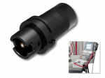
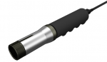
Machine-Integrated Drawbar Force Gauges
The machine-integrated drawbar force gauge automates drawbar force measurement. With a wireless force sensor stored in the tool changer, a machine can periodically automatically check the drawbar without stopping production. Drawbar force is returned to the machine control via a wireless receiver, automatically alerting the operator if insufficient force is detected.

Manual Mechanical Self-locking Drawbar Style Clamping Systems
The manually actuated drawbar style die clamping system is designed for clamping dies of various widths on press slides and tables. The self-locking eccentric cam gear guarantees a simple handling with a maximum of safety.
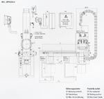
Manual Hydro-mechanical Self-locking Drawbar Style Clamping Systems
The hydromechanical self-locking (hydrolock) drawbar style die clamping system is designed for clamping dies of various widths on press slides. The clamping actuator can be moved manually in the T-slot of the press slide between the parking position and the respective die. Hydraulic pressure is at a maximum 90 bar.
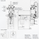
Automatic Hydro-mechanical Self-locking Drawbar Style Clamping Systems
The drawbar style hydromechanical (hydrolock) self-locking die clamping system is designed for clamping dies of various widths on press slides. The clamping actuator moves automatically in the T-slot of the press slide between the parking position and the respective die. Clamping and unclamping are performed by a hydromechanical self-locking clamping gear. Hydraulic pressure is at a maximum 90 bar.
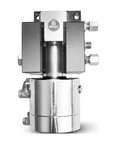
Automatic Hydraulic Drawbar Style Clamping Systems
The hydraulic die clamping system with drawbar style clamping is designed for clamping dies of different widths on press slides. The clamping actuator moves automatically into the T-slot of the press slide between the parking position and the respective die. The clamping element can clamp different clamping rim heights due to the long clamping stroke of the double acting cylinder. Hydraulic pressure is at a maximum 400 bar.
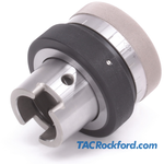
HSK Drawbar Sensor Position Gauges
Drawbar position gauges are used to adjust and set drawbar stroke position on HSK machine tool spindles. The gauges allow the clamping angle to be adjusted to the high and low limits, allowing the stroke position to be set.
Workholding Collet Drawbar Force Gauge
ForceCheck collet force gauges measure the drawbar pullback force of a 5C, 16C, or 20C collet workholding system. Measurement of collet drawbar force provides an easy way to ensure correct force from machine to machine, or between setups for different parts.
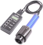
Drawbar Clamping Force Gauges, Wired
Tool clamping force is often never measured after a machine is put into service. Regular verification allows problems to be detected early so maintenance and repairs can be scheduled. As a result, emergencies and unexpected downtime can be avoided. When troubleshooting, drawbar performance can quickly be verified.
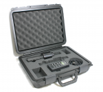
Drawbar Clamping Measuring Bars
This critical performance -- the tool clamping force -- is often never measured after a machine is put into service. Regular verification allows problems to be detected early so maintenance and repairs can be scheduled. As a result, emergencies and unexpected downtime can be avoided. When troubleshooting, drawbar performance can quickly be verified.